
A circuit breaker panel is a critical component in electrical systems, distributing power and protecting circuits from overcurrent. It ensures safety and reliability in residential and commercial setups, with wiring diagrams simplifying installation and troubleshooting processes.
1.1 Understanding the Basics of Circuit Breaker Panels
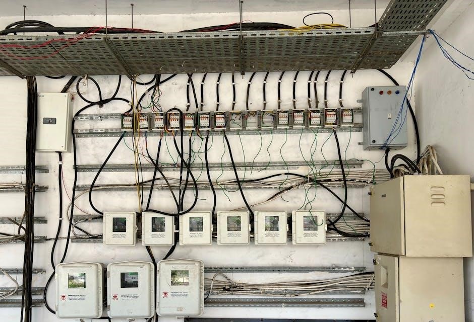
A circuit breaker panel is the central hub of an electrical system, housing circuit breakers that protect circuits from overcurrent. It consists of a main breaker controlling the entire panel and individual breakers for specific circuits. Wiring diagrams, often provided in PDF formats, visually represent the panel’s layout and connections, simplifying installation and troubleshooting. Understanding the basics involves familiarizing oneself with the panel’s components, such as bus bars, connectors, and wiring, ensuring safe and efficient electrical distribution. This knowledge is essential for homeowners and electricians alike, enabling them to identify and resolve issues effectively while maintaining electrical safety and system reliability.
1.2 Importance of Wiring Diagrams in Electrical Systems
Wiring diagrams are essential tools in electrical systems, providing a visual representation of circuit connections and components. They enable electricians and DIYers to understand how circuits are configured, simplifying installation, troubleshooting, and maintenance. For circuit breaker panels, these diagrams detail the layout of breakers, buses, and wiring, ensuring safe and efficient system operation. By referencing a wiring diagram, individuals can identify potential issues, such as overloaded circuits or incorrect connections, before they lead to hazards. Additionally, diagrams help in planning upgrades and ensure compliance with electrical codes, making them indispensable for both professionals and homeowners working with circuit breaker panels and their wiring configurations.
Key Components of a Circuit Breaker Panel
A circuit breaker panel consists of essential parts like circuit breakers, buses, and wiring, ensuring safe and efficient power distribution and overload protection in electrical systems.
2.1 Essential Parts of a Circuit Breaker Panel
A circuit breaker panel comprises several key components. The main breaker controls the entire electrical supply, while individual circuit breakers protect specific circuits. The bus bars distribute power, and wiring connects components. The neutral bar and ground bar ensure safe current flow. The enclosure houses all parts securely. These elements work together to provide reliable power distribution and overload protection. Understanding these parts is crucial for interpreting wiring diagrams and ensuring system safety; Proper installation and maintenance of these components are vital for preventing electrical hazards and ensuring optimal performance. Wiring diagrams in PDF formats often detail these parts for clarity.
2.2 Role of Circuit Breakers in Electrical Systems
Circuit breakers are essential for protecting electrical systems from damage caused by overcurrent conditions. They act as automatic switches, interrupting the circuit when excessive current is detected. This prevents overheating, fires, and equipment damage. In a circuit breaker panel, each breaker corresponds to a specific circuit, ensuring localized protection. They also provide a safe way to manually disconnect power for maintenance. Wiring diagrams in PDF guides often illustrate how breakers are connected within panels, aiding in installation and troubleshooting. Their role is critical for maintaining safety, reliability, and efficiency in both residential and industrial electrical setups. Regular inspection of breakers is recommended to ensure optimal performance and safety.
Reading and Interpreting Wiring Diagrams
Wiring diagrams are crucial for understanding circuit connections in breaker panels. They provide a visual guide to installing, troubleshooting, and maintaining electrical systems safely and efficiently.
3.1 Decoding Circuit Breaker Panel Schematics
Decoding circuit breaker panel schematics involves interpreting symbols and connections. These diagrams use standardized notation to represent components like breakers, buses, and wires. Understanding the layout helps in identifying power sources, branch circuits, and control elements. Schematics often include labels for each breaker, indicating their respective loads. Color coding may differentiate between phases and neutral lines. Detailed diagrams also show how components interact, aiding in troubleshooting and ensuring safe modifications. Familiarity with these schematics is essential for electricians to diagnose issues efficiently and perform precise repairs or upgrades to the electrical system. Proper decoding ensures compliance with safety standards and optimal system performance.
3.2 Common Symbols and Notations in Wiring Diagrams
Wiring diagrams use standardized symbols to represent components, ensuring clarity and consistency. Common symbols include circles for circuit breakers, lines for wires, and parallel lines for buses. Notations like “L1,” “L2,” and “N” denote live and neutral phases. Symbols for ground wires, fuses, and switches are also prevalent. These elements are arranged to illustrate connections and power flow. Color coding may differentiate between phases or highlight critical pathways. Understanding these symbols is essential for interpreting diagrams accurately, enabling safe and efficient electrical work. Proper notation ensures that even complex systems are comprehensible, aiding in installation, troubleshooting, and maintenance of circuit breaker panels.
Installation and Mounting of Circuit Breaker Panels
Proper installation and mounting of circuit breaker panels ensure safe and efficient electrical system operation. Follow manufacturer guidelines for secure mounting and connections to avoid hazards and ensure reliability.
4.1 Step-by-Step Guide to Installing a Circuit Breaker Panel
Installing a circuit breaker panel requires careful planning and adherence to safety protocols. Begin by shutting off the main power supply and verifying zero voltage using a multimeter. Mount the panel securely on a wall, ensuring it is level and accessible. Next, connect the main electrical lines to the panel’s terminals, following the wiring diagram provided in the circuit breaker panel wiring diagram PDF. Install individual circuit breakers, starting with the main breaker and then adding branch breakers for each circuit. Finally, label each breaker for easy identification and test the system to ensure proper functionality and safety.
4.2 Proper Mounting Techniques for Circuit Breaker Panels
Proper mounting of a circuit breaker panel ensures safety, accessibility, and compliance with electrical codes. Begin by selecting a location that is easily accessible but protected from moisture and extreme temperatures. Use a spirit level to ensure the panel is perfectly straight before securing it to the wall. Anchor the panel firmly using wall anchors or screws suitable for the surface, such as drywall or concrete. Ensure the panel is installed at a height that allows easy access, typically between 4 to 6 feet from the floor. Refer to the circuit breaker panel wiring diagram PDF for specific mounting requirements. Always follow local electrical regulations and safety standards to guarantee a secure installation.
Safety Guidelines for Working with Circuit Breaker Panels
Always disconnect power before working on a circuit breaker panel. Use insulated tools, wear protective gear, and ensure the area is well-ventilated to prevent electrical hazards.
5.1 Essential Safety Precautions When Handling Electrical Panels
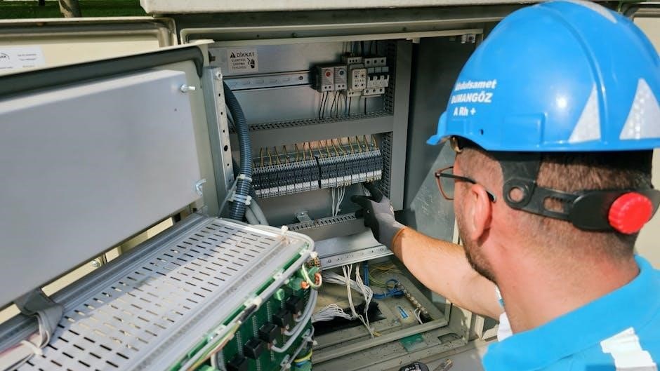
When working with circuit breaker panels, always turn off the main power supply and verify voltage absence using a multimeter. Wear insulated gloves and safety goggles to protect against electrical shocks. Ensure the work area is well-lit and clear of flammable materials. Never touch electrical components with bare hands or metal objects. Use properly rated tools to avoid damage or short circuits. Familiarize yourself with the wiring diagram to understand the panel’s layout and connections. Keep a fire extinguisher nearby and avoid overloading circuits. If unsure, consult a licensed electrician to prevent accidents. Safety should always be the top priority.
5.2 Best Practices for Avoiding Electrical Hazards
To avoid electrical hazards, always refer to the circuit breaker panel wiring diagram for accurate connections. Regularly inspect panels for signs of wear or damage. Ensure all wires are securely connected and properly labeled. Use tools with insulated handles to prevent shock. Never overload circuits, as this can cause tripping or fires. Keep panels in well-ventilated areas to prevent overheating. Test circuit breakers periodically to ensure proper function. Avoid touching live wires or components without proper insulation. Follow manufacturer guidelines for installations and repairs. Keep emergency contact information nearby. By adhering to these practices, you can significantly reduce the risk of electrical accidents.
Troubleshooting Common Issues in Circuit Breaker Panels
Use wiring diagrams to identify faulty circuits. Check for tripped breakers, loose connections, or overloaded circuits. Verify power sources and test circuits to ensure proper functionality.
6.1 Identifying and Resolving Common Circuit Breaker Problems
Common issues include tripped breakers, overloaded circuits, and faulty connections. Refer to the wiring diagram to locate the problematic circuit. Check for loose wires or damaged components. Reset tripped breakers and ensure loads are balanced. Replace faulty breakers or connections as needed. Regular maintenance can prevent recurring issues. Always disconnect power before performing repairs. Use the diagram to trace circuits and verify connections, ensuring safe and efficient troubleshooting.
6.2 Diagnostic Tips for Wiring Diagrams and Panel Issues
When diagnosing issues with your circuit breaker panel, start by reviewing the wiring diagram to identify potential fault points. Use a multimeter to test voltage and continuity in suspect circuits. Check for tripped breakers, loose connections, or overloaded circuits. Verify that all wires are connected correctly according to the diagram. If a breaker trips repeatedly, investigate the connected devices or appliances for faults. Ensure the panel is properly grounded and balanced to avoid overloading. Refer to the wiring diagram to trace circuits and isolate problematic areas. Regularly inspecting the panel and its connections can prevent unexpected issues and ensure safe operation. Always consult the wiring diagram for guidance.
Resources and Further Reading
Explore detailed PDF guides and manuals for circuit breaker panels, offering comprehensive wiring diagrams and installation tips. Utilize online tools and tutorials for in-depth understanding and practical applications.
7.1 Recommended PDF Guides and Manuals for Circuit Breaker Panels
For comprehensive understanding, download PDF guides like “Circuit Breaker Panel Wiring Diagrams” and “Electrical Panel Installation Manuals.” These resources provide detailed schematics, installation steps, and safety tips. They cover various panel types, from residential to industrial, ensuring clarity for different applications. Additionally, manuals from manufacturers like Eaton offer specific instructions and diagrams, making them invaluable for technicians and DIYers. These guides are essential for troubleshooting and ensuring compliance with electrical standards. They also include troubleshooting sections and best practices, enhancing both safety and efficiency in electrical work.
7.2 Online Tools and Tutorials for Understanding Wiring Diagrams
Several online tools and tutorials simplify understanding wiring diagrams for circuit breaker panels. Websites like Eaton and ManualsLib offer detailed PDF guides and interactive diagrams. Platforms such as YouTube provide step-by-step video tutorials, while forums like Reddit and ElectricalHub share practical insights. Tools like Fritzing and ElectraSchematics allow users to create and analyze custom diagrams. Many manufacturers provide free resources, ensuring accessibility for professionals and DIYers alike. These tools enhance learning and application, making complex electrical systems more approachable. They are invaluable for troubleshooting and ensuring safe, efficient installations.